Input
Inputs nodes are nodes that creates base geometry. Some input nodes have input sockets but this is so that the Grid Node is calculated before reaching that node or so that their settings can be accessed outside of group nodes. These nodes with inputs will replace the incoming coordinates with their own.
Convert Grid
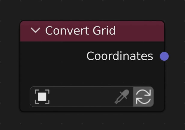
Takes an existing object, checks if it is a grid, then applies the node tree to it.
Does not make changes on chosen object if it is not the active object
Object
Use the picker to choose a visible object in the 3D Viewport
Click the blank space to choose an object from a list
Will check to make sure the chosen object is a grid made up of only quadralaterals (4-sided polygons) connected in a grid or checkerboard pattern where the overall shape of the object is a quadralateral and each inner vertex is only has 4 connected faces and 4 connected edges.
Update Object
Update the object. Will check to make sure object is still a grid
Grid Checking
Perfect Grid
A perfect grid has the following requirements to be used by NodeScapes
- Made up of only quadralaterals (4-sided polygons)
- Overall shape is also a quadralateral
- Side vertices only connect to 2 faces and 3 edges
- Inner vertices only connect to 4 faces and 4 edges
- The vertex indices increase predictably
- i.e. increases by 1 or the previous index + number of vertices in a row or column
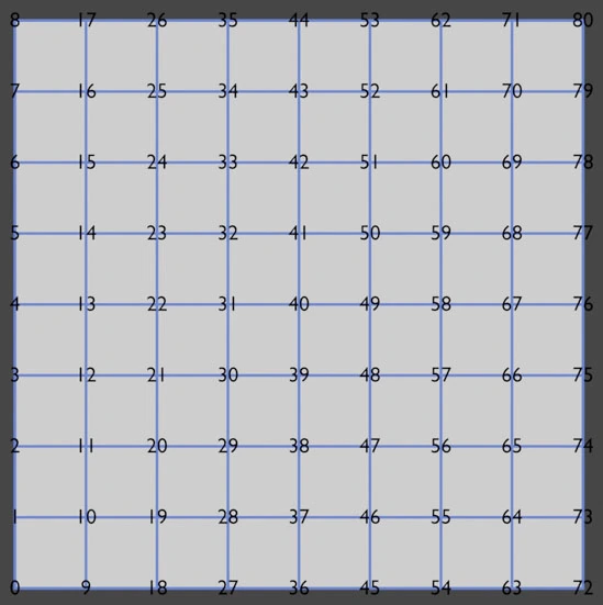
Perfect Grid
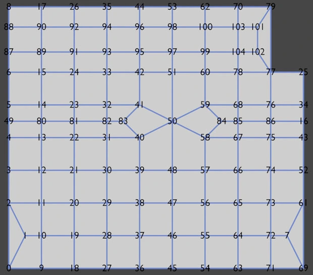
Imperfect Grid
Get Geometry Attribute
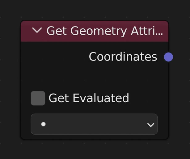
This node lets you select an exist attribute saved in 'bpy.context.object.data.attributes'. Attributes created and edited by Geometry Nodes can be accessed here.
Get Evaluated
This will make sure to grab attributes after all of the modifiers are calculated such as grabbing an attribute after Geometry Nodes has been calculated.
Attribute
This is the attribute picker where existing attributes will show up to be chosen. If 'Get Evaluated' is on this will show attributes after modifiers are calculated (ie Geometry Nodes)
Grid
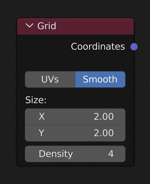
Creates a grid (plane) of the given size and density.
Warning
Every time you change the Size or Density all mesh data (UVs, Vertex Weights, Vertex Colors) are changed! Materials and modifiers (such as particles) stay the same though
UVs
Whether or not to create UVs when creating a new plane
Smooth
Smooth normals
Note
Toggling this does not recreate the object or even execute the rest of the nodes
Size
Dimensions of the plane in the X and Y directions
Density
Subdivision Level/Resolution of the Plane. Independent of Size Basically how many faces per axis for a 1x1 plane.
Example
- A plane with a size of 1x1 and Density of 50 results in a plane with 50 faces along the X-axis and 50 faces along the Y-axis (2500 faces total in the plane)
- A plane with the same Density (50) with the size of 1x2 results in a plane with 50 faces along the X-ais and 100 faces along the Y-axis (5000 faces total)
- Generally a Density of 64 with a size of 1x1 gets real-time results while a Density up to 200 and size up to 2x2 will still give effectively a real-time result
Image
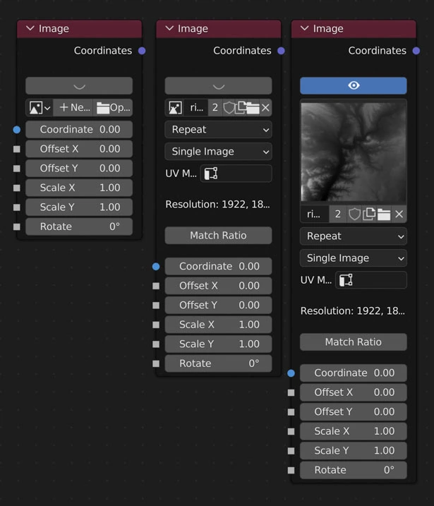
Returns an image (1D array of floats) from which to displace vertices.
Image
Pick an image to use when displacing
Discards all color information except the red channel. The “color space” and view as render” make no difference to the pixel values with NodeScapes
Extension
How the image is extrapolated past its bounds when UVs are outside of the image in the UV editor (extend past the 0-1 range).
- Repeat
- Cause the image to repeat in the x and y axes
- Mirror
- Cause the image to repeat in the x and y axes flipping the image in both axes every other repeat
- Repeat Edge
- Repeat the edge pixels beyond the boundaries
- Clip
- Do not extend the image. Any vertices that are outside the image bounds will be set to 0.
Source
From where the image comes
UV Map
Select what UV Map to use when mapping the image to vertices
Match Ratio
Matches the Grid Node’s size ratio to the selected image’s size ratio
Coordinates
Connect the coordinates of the Grid Node here. This makes sure the image node updates correctly when the Grid Node does. Any node calculations done between the Grid Node and image are ignored and needlessly take up precious compute time
Warning
Every time you change the Size or Density of the Grid Node all non-NodeScapes created mesh data (UVs, Vertex Weights, Vertex Colors) are removed! Materials and modifiers (such as particles) stay the same
Example
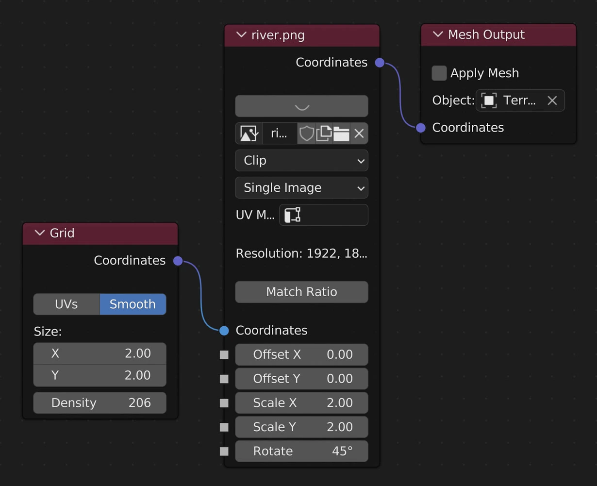
Example Image Layout
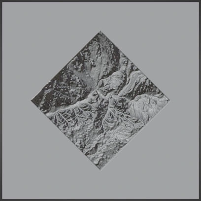
Extension: Clip
Extension: Repeat
Extension: Mirror
Extension: Repeat Edge
Noise Base
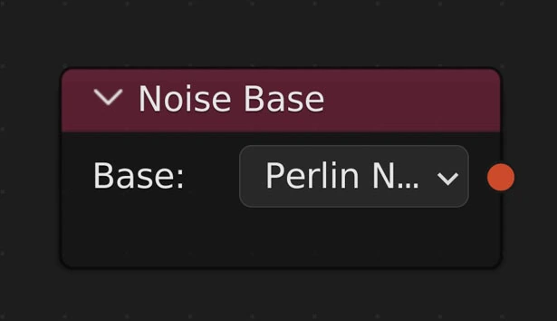
Returns a noise base for noise nodes
Noise Base Options
- Blender
- Perlin New
- Voronoi F1
- Voronoi F2
- Voronoi F3
- Voronoi F4
- Voronoi F1F2
- Voronoi Crackle
- Cell Noise
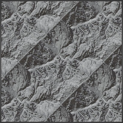
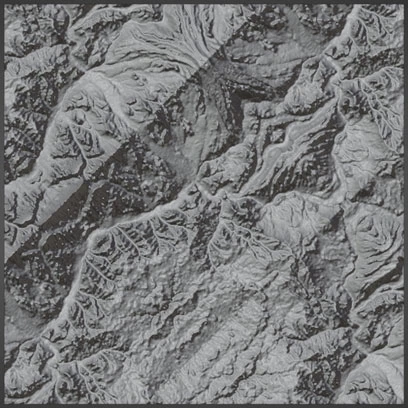
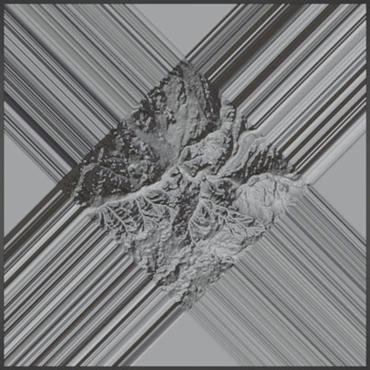
Example
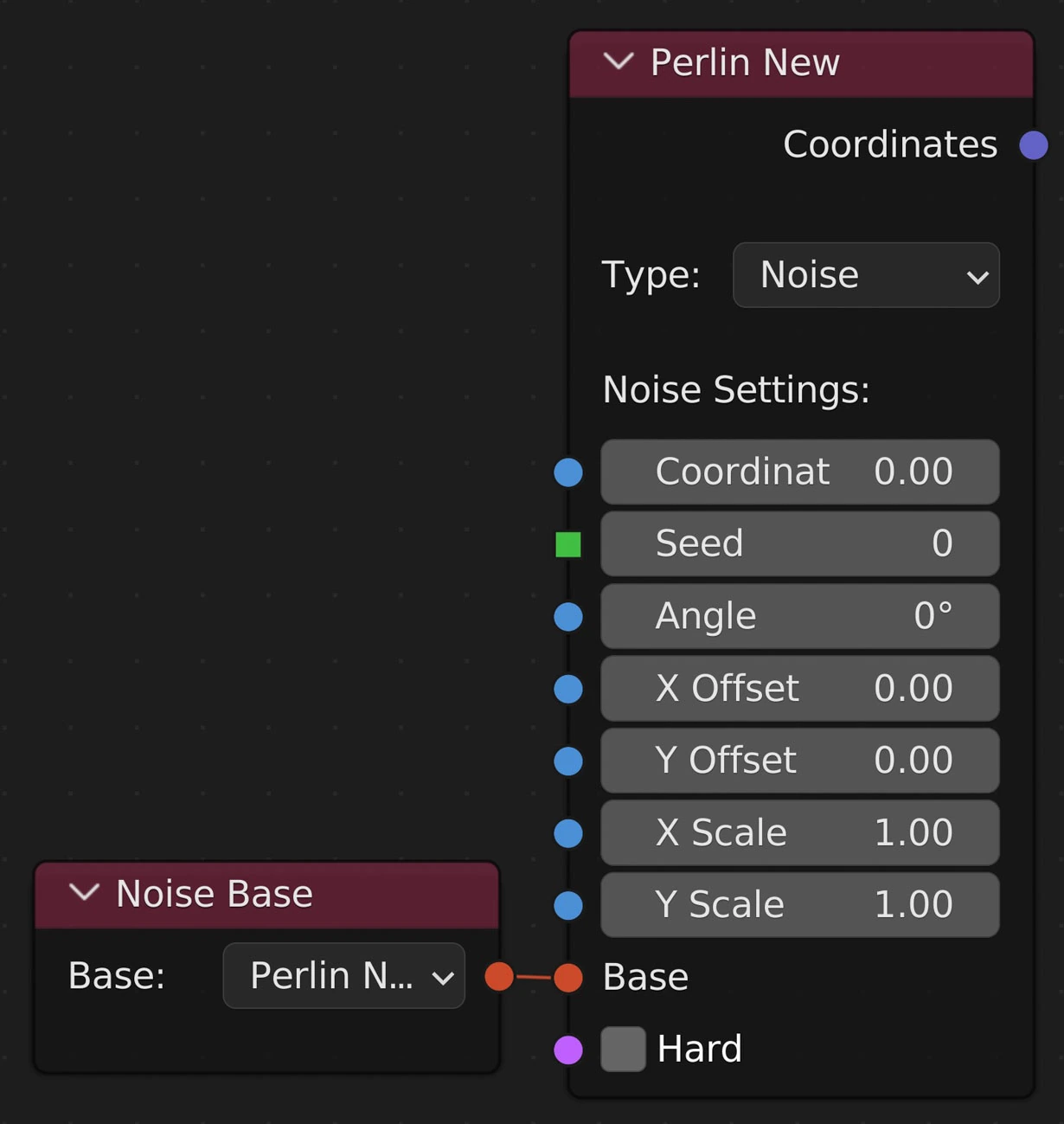
Noise Base connected to a Noise node
Object Data
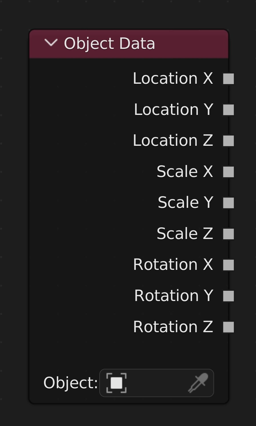
Enables control of properties via an object's transform data. When node is selected and the chosen object is transformed the NodeScapes node tree will update automatically
Transform Data
Location (X,Y,Z), Scale (X,Y,Z), Euler Rotation (X,Y,Z)
- Outputs the chosen object's transform data of respective type and axis
Object
The object from which to export transform data
Auto-Update
When the Object Data node is selected and the chosen object is transformed (moved, scaled, rotated) the node tree will auto-update in as real-time as possible with respect to Density and other nodes in tree.
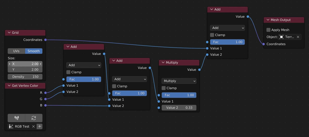
Get Vertex Colour
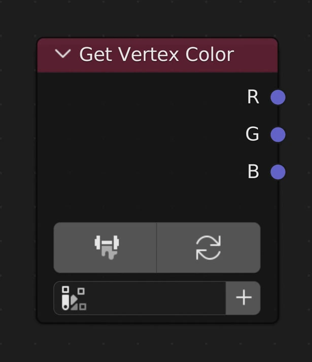
Returns the values from the selected Vertex Color layer. Each color output channel (R, G, B) will be from 0 to 1. Useful for mixing
Save from Vertex Colors Mode
Clicking this button will ensure the mesh is up to date with respect to where it is inputted in the node tree and enter into the Vertex Painting Mode. Once entering Object Mode once again any changes will be saved and useable in the node tree
Clear Colors
Clear currently saved colors
Vertex Color Layer
The Vertex Color layer to use
Create New Vertex Color Layer
Create a new Vertex Color layer and set it as the active layer on the node
RGB Outputs
Returns the color channel of that name (R: red, G: green, B: blue)
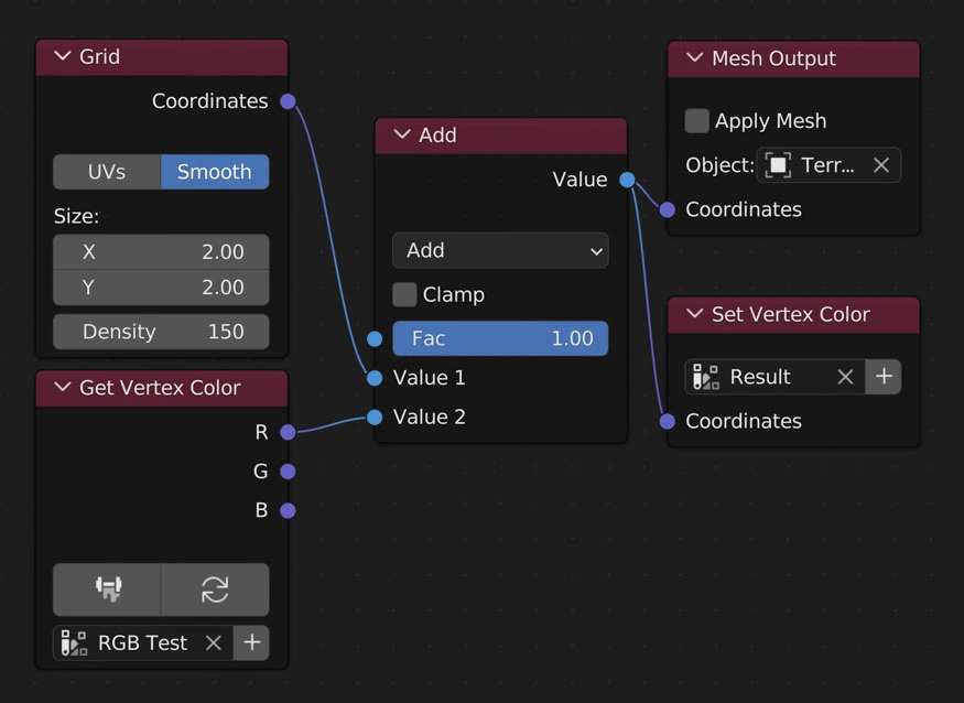
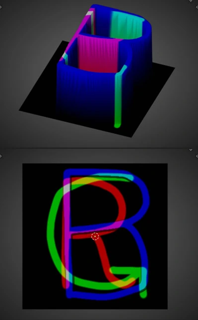
Example
| Vertex Color Example Node Layout | Example Vertex Color Layer |
|---|---|
 |
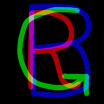 |
Info
Here we are using a Vertex Color layer as straight displacement to see the relation between the colors and separating them
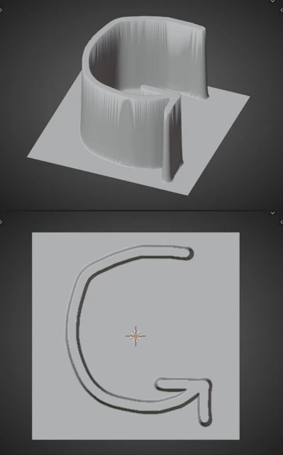
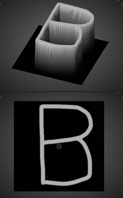
Outputting Red Channel
| Geometry | Geometry with Color | Result |
|---|---|---|
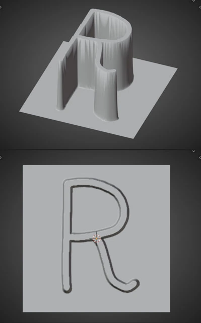 |
 |
 |
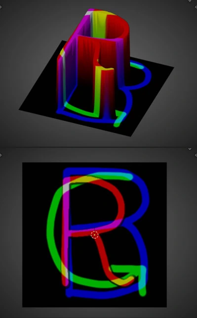
Outputting Green Channel
| Geometry | Geometry with Color | Result |
|---|---|---|
 |
 |
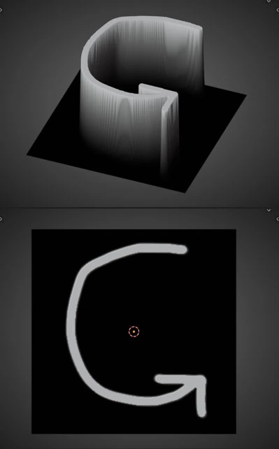 |
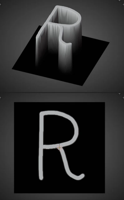
Outputting Blue Channel
| Geometry | Geometry with Color | Result |
|---|---|---|
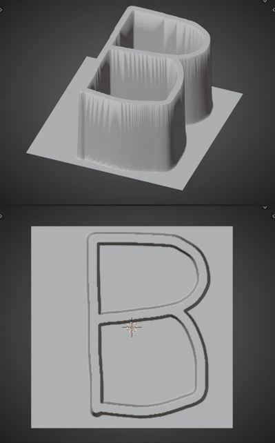 |
 |
 |
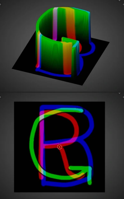
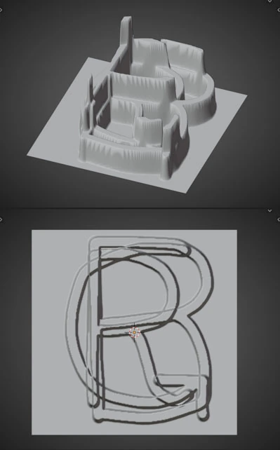
Adding All Channels Together
Vertex Color Example Node Layout
Here we are adding all of the channels together just for fun. The more channels that overlap at a vertex the greater the vertex height
| Geometry | Geometry with Color | Result |
|---|---|---|
 |
 |
 |
Get Vertex Weights
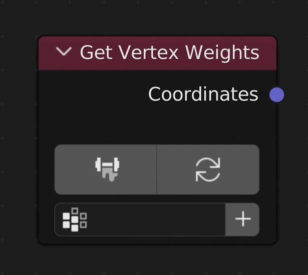
Returns the values from the selected Vertex Weight layer. Each weight will be between 0 and 1. Useful for mixing.
Save from Vertex Weights Mode
Clicking this button will ensure the mesh is up to date with respect to where it is inputted in the node tree and enter into the Weight Painting Mode. Once entering Object Mode once again any changes will be saved and usable in the node tree
Clear Weights
Clear currently saved weights
Vertex Weight
The Vertex Weight layer vertex weight layer to use
Create New Vertex Weight Layer
Create a new Vertex Weight layer and set it as the active layer on the node
Examples
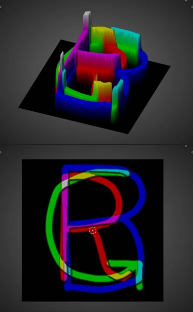
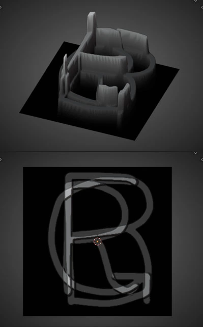
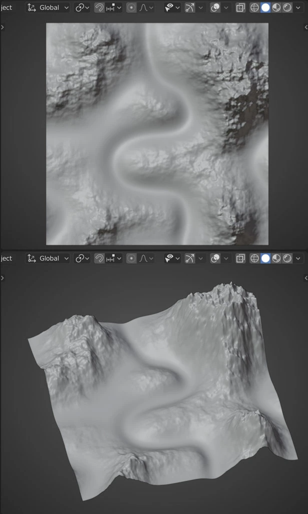
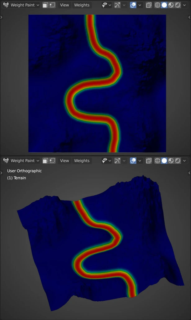
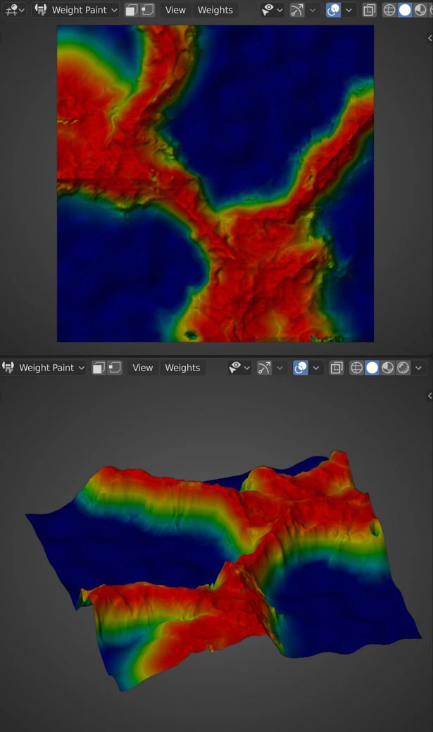
River
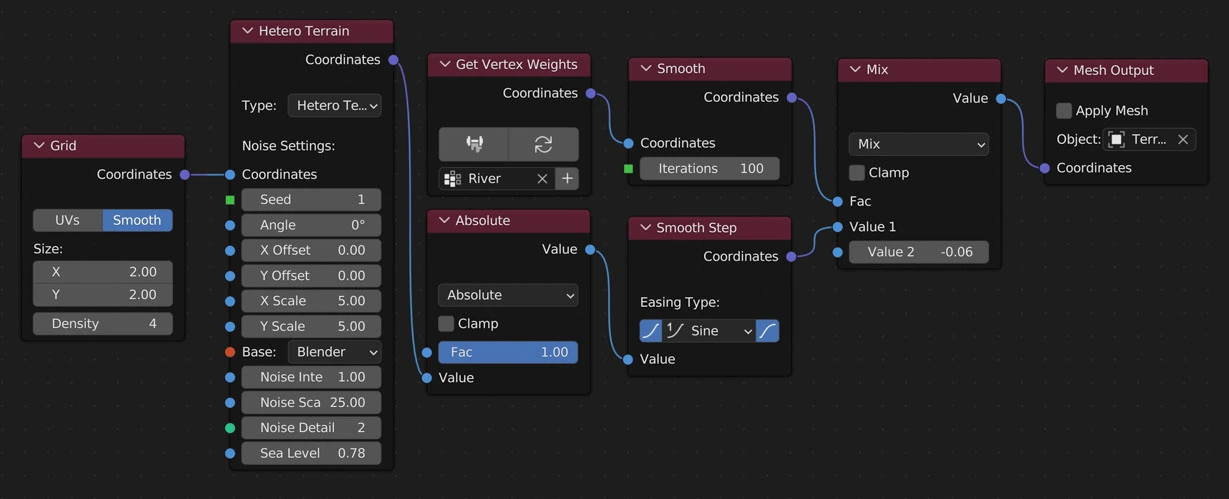
Node River Layout
Info
Here we are using a vertex weight map as the Factor to mix between a base value (-0.06) for the river bottom and the terrain (Hetero Terrain node)
| Result | Vertex Wight Map |
|---|---|
 |
 |
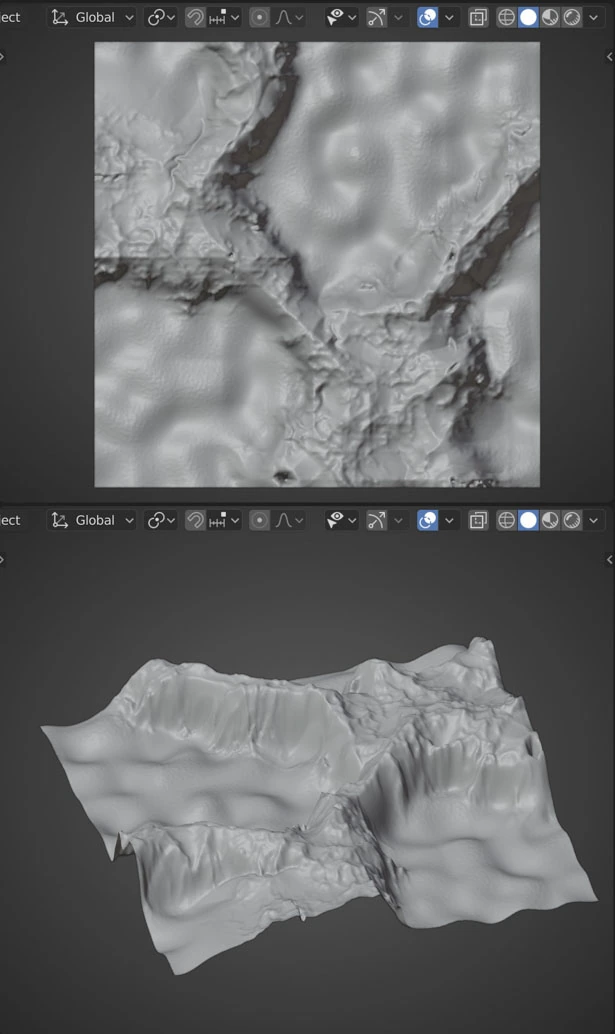
Mountains
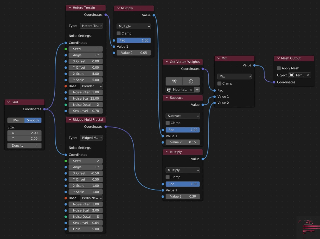
Node Mountains Layout
Info
Here we are using a vertex weight map as the Factor to mix between a base landscape (Hetero Terrain node) and a mountainous landscape (Ridged Multi Fractal node)
| Result | Vertex Wight Map |
|---|---|
 |
 |
Value Nodes
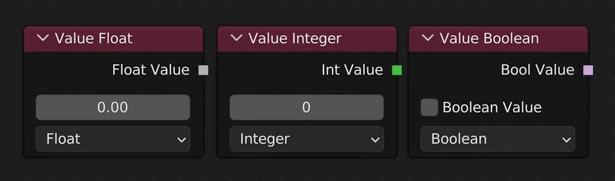
Inputs numerical values to other nodes in the tree.
Value Type
Change the value type
Output Types
| Float | Int (Integer) | Boolean |
|---|---|---|
| Returns a float value | Returns an integer value | Returns a True or False value |
| 1.0, 2.1, 5.12784 | 1, 2, 5 | True, False |
Note
Similar to the Value node in Shader Nodes